
Working process
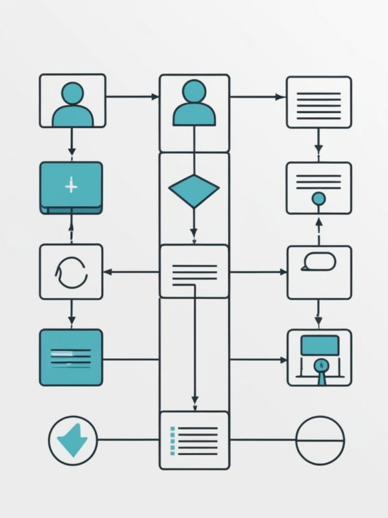
Workflow
First, I’ll call or email the client to discuss exactly what they want. Once the idea takes shape, I’ll put together a documentation package that outlines the technical details, and I’ll jointly approve it with the client. Once I get the green light, I’ll prepare a detailed price quote that includes all expenses necessary for the project’s implementation, covering both design fees and material costs.
Once the quote is accepted, I’ll start the work and provide regular updates based on the client’s needs. I recommend having ongoing ‘follow-up’ meetings throughout the project, whether via email or online meetings, to ensure both parties have enough information. If any questions arise during the project, we can revisit the terms, and the implementation of new functions can also be discussed, keeping in mind that this may incur extra costs
I ensure that the project is always accompanied by appropriate documentation related to its technical content, allowing the client to manufacture and further develop the requested products independently.
Embedded Software Design Process
Embedded software development presents special challenges, as these programs are typically hardware-bound, operate with limited resources, and often need to run in real-time systems. A general development process is outlined below:
Requirements and specification definition
The first step is to develop a detailed specification of the project goals and requirements. This includes:
- Functional requirements: What does the software need to know?
- Non-functional requirements: For example, performance, memory usage, power consumption.
- Hardware specifications: What microcontroller, peripherals, and communication channels does the system use?
Architecture design
Designing the system architecture, which includes:
- Hardware-software interface: How the software communicates with the hardware. What necessary functions the system must include on the software or hardware side.
- Modular design: The separation of software components, such as peripheral controllers, communication protocols, and application logic. Standardization of necessary libraries and their integration into the embedded software.
- Operating system: If necessary, I develop the software’s operation through a special operating system (for example, RTOS), but for simpler and more optimization-demanding solutions, I use a special solution without an operating system.
Preparation and definition of development environment
Definition of the required software environment
- Development environment: I will perform the development in the development environment required for the chosen hardware environment. In the case of more complex projects using multiple microcontrollers, multiple environments will be used in parallel.
- Need for simulation: In some cases, it may be necessary to perform simulations to validate the system before starting the project.
- Version control: Git or other version control system.
Code Development
The creation of the actual software code, which usually consists of the following steps:
- Drivers: To manage hardware components such as sensors, communication modules, and displays.
- Middleware: For example, the implementation of protocols such as I2C, SPI, UART, or Ethernet.
- Application Logic: To implement and realize the higher-level functions of the system
Testing and debugging
Testing the software developed for the system
- Unit testing: Testing individual modules, in some automated environment.
- Integration testing: Testing modules together.
- System testing: Testing the entire software on the hardware.
- Debugging: Locating and fixing errors, then evaluating the tests
Optimization
Since embedded systems often have limited resources, or are required by capabilities/requirements, I optimize the software based on the following aspects:
- Memory usage: Efficient management of RAM and flash memory.
- Power consumption: Designing low-power modes for optimized battery usage (in the case of battery-powered solutions).
- Performance: Scheduling critical tasks, thus achieving more optimal processor power distribution.
Documentation
During the development process, documents are continuously created:
- Operating Instructions: A document containing the minimum information required to use the system.
- User Manual: The most important information required to use the software at the user level.
- Developer Documentation: Explanation of source code and architecture for possible further development of the software.
- Maintenance Guide: A document containing the foreseeable maintenance needs of the system.
Implementation and maintenance
In more complex and specialized cases, follow-up on the completed software is required.
- Installation: Loading the final software onto the target hardware by me as the developer-
- Maintenance: Fixing bugs and adding new features as needed.
- Update management: Making updates as needed

PCB Design process
Defining Requirements and Specifications
The first step is to define the project goals and technical parameters:
Requirements and specification definition
The first step is to develop a detailed specification of the project goals and requirements. This includes:
- Electrical requirements: Determine the planned voltage and load levels. Define the required functions, even with predefined components.
- Mechanical requirements: Size, shape, type and location of connectors, number of layers.
- Environmental conditions: Temperature range, moisture resistance, vibration resistance, mechanical load
- Manufacturing requirements: Panel thickness, material (e.g. FR-4), required manufacturing accuracy
Basic Hardware Design
Based on the preliminary discussions, outlining the concept of the system to be implemented:
- Schematic: Schematic drawing of the electronic circuit. Definition of basic hardware connections.
- Component Selection: Selection of appropriate components (active, passive components and ICs) based on availability, price and performance.
- Bill of Materials (BOM): Preparation of a parts list that includes the name, type, part number and quantity of the components as well as sourcing options.
PCB Layer Structure Design
Preparation of PCB design based on predefined parameters
- Determine the number of layers: Select single-sided, double-sided, or multilayer PCB based on complexity.
- Determine the layer structure: E.g. define ground (GND) and power (VCC) layers.
- Define design rules: Trace widths, pad sizes, layer spacing, and other DRC (Design Rule Check) rules
Component Placement
When designing a PCB, it is necessary to arrange the components logically and efficiently:
- Logical layout: Ensuring the proximity of the components that are connected to each other.
- Mechanical constraints: Placing the connectors, mounting points, and heat sinks taking into account the physical constraints.
- Thermal considerations: Keeping large heat-generating components away from other critical components.
- Noise considerations: It is necessary to separate the noise-generating and noise-sensitive parts. This can often be solved with robust GND foils, but in special cases it is necessary to isolate these two groups.
Routing
The routing ensures the implementation of electrical connections between components:
- Power and grounding: Design of power lines and grounding network (GND plane) with special attention to the nature of the predefined loads.
- Signal lines (signal traces): Optimization of traces required for high-frequency signals (e.g. impedance matching).
- Differential pairs: If necessary, precise design of signal pairs (e.g. USB, Ethernet) to preserve signal integrity.
- Interlayer vias: Connecting traces between different layers for more complex PCB designs
Verification and Simulation
After routing, the completed project needs to be verified
- DRC (Design Rule Check): Automatic verification of compliance with design rules performed by the design software
- Simulations: For example, thermal analysis, if necessary, electromagnetic interference (EMI) and signal integrity testing either by simulation or laboratory tests.
- Gerber files: Review of files required for manufacturing, checking manufacturer compatibilit
Preparation of manufacturing documentation
Creating the files and documents required for PCB fabrication and placement:
- Gerber files: Description of the layers required for PCB fabrication.
- Component placement: Contains the exact position and orientation of the components.
- Assembly drawings: Drawings required for manual placement or testing
- 3D model: 3D model generated from completed designs
Mechanical Design Process
I undertake the creation of simple mechanical designs necessary for prototyping.
Consultation and needs assessment
During the consultation with the client, we jointly determine exactly what kind of 3D model they want.
Important aspects:
- Function and size of the object to be designed.
- Definition of simple shapes and details.
- Declaration of mechanical stress
- Required special mechanical connections (e.g. form-locking, force-tight connections)
- Format and intended use (e.g. 3D printing, visualization).
- If necessary, the client provides drawings, sketches or references.
Creating a basic model
Based on the completed notes, I create a model with basic functions, which we discuss again with the client:
- Creating a simple 3D model
- The completed model is built from simple shapes (e.g. cubes, cylinders, spheres).
- Exact adherence to the dimensions and proportions specified by the client.
- Creating a first version and presenting it to the client for approval.
Modifications and fine-tuning
Based on feedback received from the pre-built model, I make modifications to the final model:
- Making minor modifications based on client feedback (e.g. adjusting proportions, details or positions).
- Finalizing the model as approved by the client.
- Checking the file to ensure compatibility for the given purpose (e.g. 3D printing)
Model handover
Export of the final 3D model in the required format.
Files handed over to the client:
- The final model in the agreed formats
- Sketches or simple demonstration images of the model if required.
- Further technical advice if necessary (e.g. setup suggestions for 3D printing).
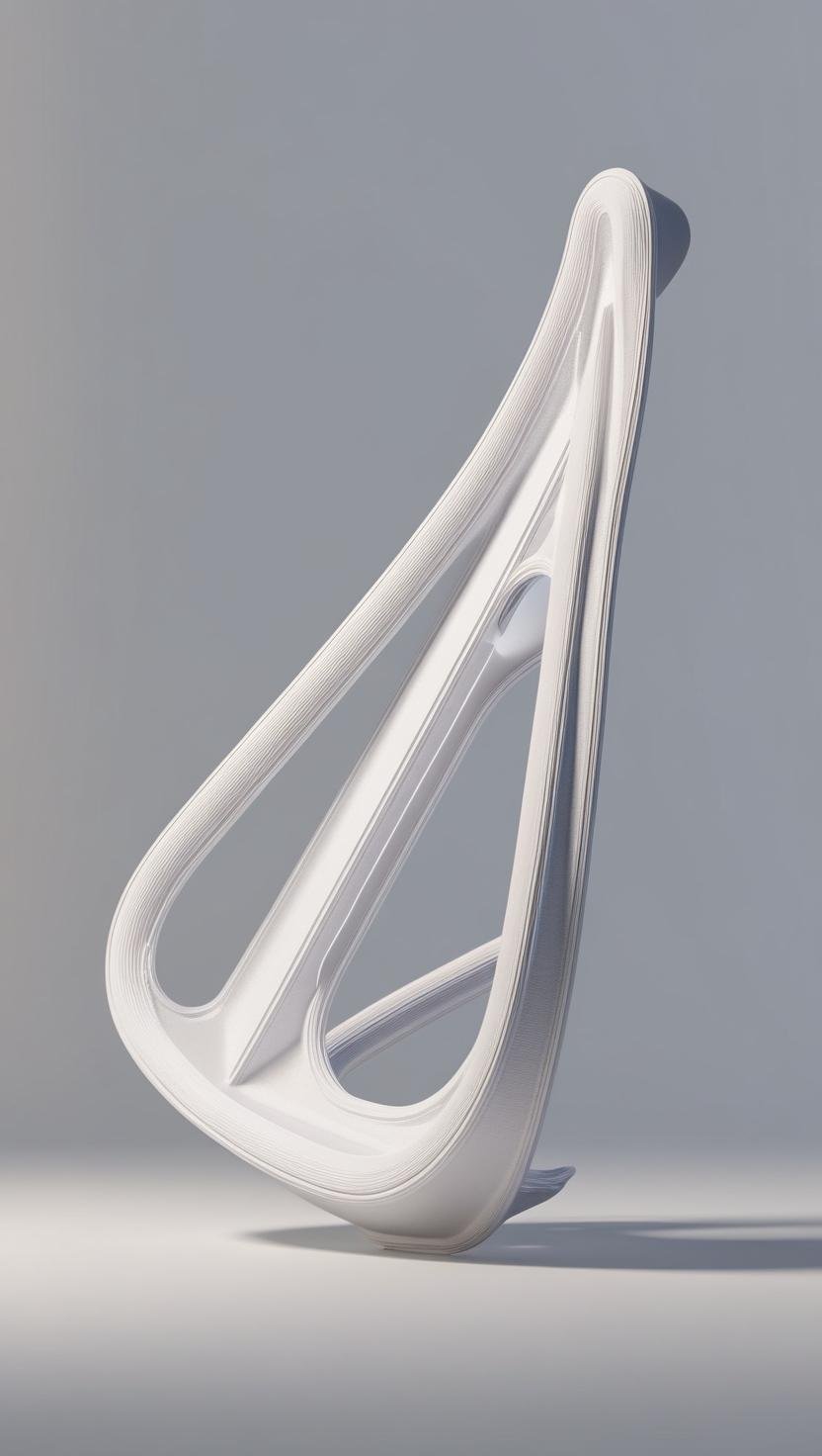
3D Printing Process
Defining Requirements and Specifications
The first step is to define the project goals and technical parameters:
If required, I can also 3D print to create a prototype for the customer. I can produce using SLA (resin printing, ABS material) or FDM (PLA or PETG material) technology, and in larger quantities if required. Here is a general process in a few steps:
Contact and requirement assessment
- The customer provides a general description of the printing parameters, the requirements of the material to be produced (e.g. function, size, quantity).
- The customer provides the 3D model required for printing (e.g. in STL, OBJ format) or asks for help in creating a simple model.
Model Check
- I thoroughly review each received file to ensure error-free printing:
- I check whether the model meets the printing requirements (e.g. complexity, bottlenecks).
- If necessary, I make suggestions for model optimization
Choosing the right technology
Based on your needs, I will help you decide which technology best suits your ideas. You can choose from the following technologies:
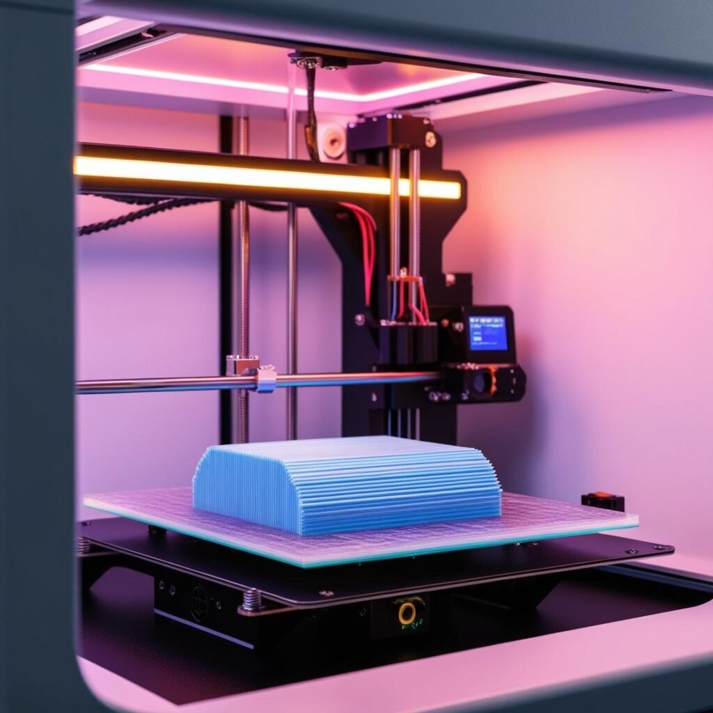
- FDM (Fused Deposition Modeling): Ideal for larger, functional prints, as a cost-effective solution. I am also able to print functional objects within certain limits, such as bearings, snap-in joints, or any shape-locking joint
- SLA (Stereolithography): Perfect for detailed, precision models, such as decorative objects or prototypes. It is important that this technology withstands less mechanical stress than FDM.
Material selection
In addition to the technology, we also select the materials together:
- For FDM printing: PLA, PETG, or even a wide range of special filaments are available.
- For SLA printing: Premium quality resins with various properties, such as transparent, high-strength or flexible versions.
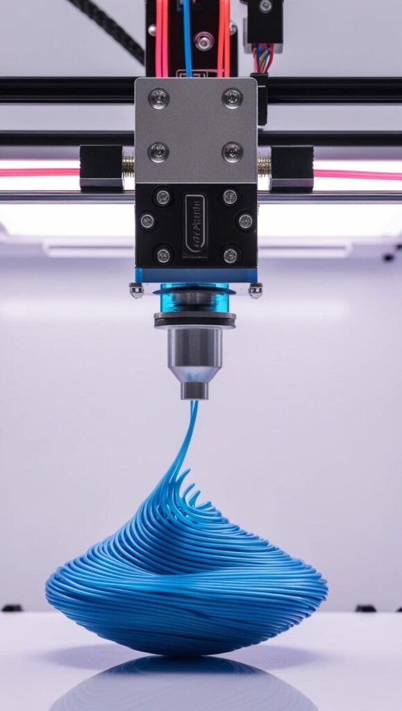
Printing
I print using the selected technology, at a pre-arranged time:
- In the case of FDM, I produce fast, cost-effective and durable prints.
- In the case of SLA, I produce models with outstanding detail and a smooth surface.
Post-processing
I process the print as required:
- For FDM models: I remove supports, sand the surface if necessary, and paint it upon request.
- For SLA models: During post-processing, I wash off the resin remaining on the model, then UV-cure and sand or polish the surface if required.
Delivery
I will deliver the finished print to you in the manner agreed upon in advance: in person, by mail or by parcel delivery.
The quality control is guaranteed in all cases, I do it myself, so you can be sure that the end result will meet your expectations.
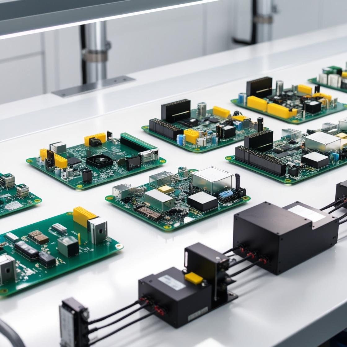
Small Batch Production Process
I am happy to design and manufacture small series of electronic devices according to your unique needs. Below I will explain how the process works and what services I offer to ensure that you are satisfied with the end result:
Needs Assessment and Consultation
As a first step, we clarify what kind of device you need:
- What is the purpose and functionality of the product?
- Is there an existing design, or should we develop the circuit and mechanical designs together?
- Let’s discuss your expectations regarding the functionality, size and budget of the device.
Preparation and prototype development
If you don’t have a ready-made plan, I will undertake the preparation of the electronic and mechanical design:
- Circuit design: Schematic preparation and PCB layout design.
- Prototyping: Production of the first samples to test the function, then small series production
- I will help you with the selection of components, taking into account availability, reliability and costs.
Production preparation
Once the prototype meets the expectations, I prepare the production process:
- BOM: Compiling and optimizing the bill of materials.
- PCB production organization: Negotiating the PCB production options, examining the time and cost requirements
- Parts procurement: Purchasing the necessary parts
- Preparation for implantation: Purchasing the necessary tools in case of a special workflow. For example, solder with a special melting point, special jigs, etc.
Small batch production
I manufacture products in small batches, in the quantities specified by you:
- PCB production and installation: I install the necessary components using manual or machine soldering as required
- Assembly of mechanical components: If necessary, assemble mechanical components (e.g. housings).
- Testing: I work with continuous monitoring of the operation of processes and devices.
Quality Control
I thoroughly inspect each manufactured part to ensure flawless operation. If required, it is also possible to provide custom test equipment:
- Functional testing based on specifications.
- Component tests based on component documentation
- Inspection to detect possible mechanical or soldering defects.
Delivery
I will deliver the finished print to you in the manner agreed upon in advance: in person, by mail or by parcel delivery.
The quality control is guaranteed in all cases, I do it myself, so you can be sure that the end result will meet your expectations.

Product Design Process
Do you need a custom electronic prototype? I can help you with the entire process, from idea to working prototype, including enclosure design if required. Below I will introduce how I work and what services I offer you.
Consultation and needs assessment
The first step is a detailed consultation:
Tell me what functions you need:
- Let us discuss the purpose of the device, its size, performance requirements and any special requirements.
- If an enclosure is also required, we will clarify the aesthetic and functional requirements.
Electronic Design
I design the electronics of the prototype based on your ideas:
- Circuit Design: I create the schematic and PCB layout.
- Component Selection: I help you find the right components, paying attention to costs and availability.
- If necessary, I also suggest alternative solutions for optimization.
Mechanical Design
If required, I also design a custom enclosure for the electronic prototype:
- I design the enclosure based on the functions and the way it will be used.
- I create the model in 3D design software, which is ready for 3D printing or other manufacturing technology.
Prototype Manufacturing
I create the working prototype based on the electronics design and the enclosure:
- The PCB and then the PCBA are manufactured: soldering and assembly are done precisely.
- If necessary, I create the enclosure using 3D printing or other manufacturing technology.
- If required, the entire prototype will undergo functional or sectional testing to ensure that it meets the requirements.
Documentation and handover
I will provide detailed documentation with the completed prototype:
- Circuit diagrams and PCB design files, if I created them
- Case design files (e.g. in STL format), if requested.
- User manual for using and testing the prototype.
- Protocols for testing if tests have been performed
Delivery
I will deliver the finished print to you in the manner agreed upon in advance: in person, by mail or by parcel delivery.
The quality control is guaranteed in all cases, I do it myself, so you can be sure that the end result will meet your expectations.